🚚 Free Worldwide Shipping on All Orders!Shop Now


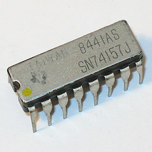
A10124 - 74191N Synchronous Up/Down Counter
The 74191N is synchronous, with reversible up/down counter having a complexity of 58 equivalent gates. The 74191N is a 4-bit binary counter. Synchronous operation is provided by having all flip-flops clocked simultaneously so that the outputs change coincident with each other when so instructed by the steering logic. This mode of operation eliminates the output counting spikes normally associated with asynchronous (ripple clock) counters.
The outputs of the four master-slave flip-flops are triggered on a low-to-high transition of the clock input if the enable input is low. A high at the enable input inhibits counting. Level changes at the enable input should be made only when the clock input is high. The direction of the count is determined by the level of the down/up input. When low, the counter counts up and when high it counts down. A false clock may occur if the down/up input is high during a load pulse.
These counters are fully programmable; that is, the outputs may be present to either level by placing a low on the load input and entering the desired data at the data inputs. The output will change to agree with the data inputs independently of the level of the clock input. This feature allows the counters to be used as modulo-N dividers by simply modifying the count length with the present inputs.
The clock, down/up, and load inputs are buffered to lower the drive requirement which significantly reduces the number of clock drivers, etc., required for long parallel words.
Two outputs have been made available to perform the cascading function: ripple clock and maximum/minimum count. The latter output produces a high-level output pulse with a duration approximately equal in width to the low-level portion of the clock output to the enable input of the succeeding counter if parallel clocking is used, or to the clock input if parallel enabling is used. The maximum/minimum count output can be used to accomplish look-ahead for high-speed operation.
Features:
Counts 8-4-2-1 BCD or binary
Single down/up count control line
Count enable control input
Ripple clock output for cascading
Asynchronously presettable with load control
Parallel outputs
Cascadable for n-Bit applications
16 pin DIP. Actual brand may vary from picture.
A10124
| Additional Resources |
$1.14
Original: $3.25
-65%A10124 - 74191N Synchronous Up/Down Counter—
$3.25
$1.14Description
The 74191N is synchronous, with reversible up/down counter having a complexity of 58 equivalent gates. The 74191N is a 4-bit binary counter. Synchronous operation is provided by having all flip-flops clocked simultaneously so that the outputs change coincident with each other when so instructed by the steering logic. This mode of operation eliminates the output counting spikes normally associated with asynchronous (ripple clock) counters.
The outputs of the four master-slave flip-flops are triggered on a low-to-high transition of the clock input if the enable input is low. A high at the enable input inhibits counting. Level changes at the enable input should be made only when the clock input is high. The direction of the count is determined by the level of the down/up input. When low, the counter counts up and when high it counts down. A false clock may occur if the down/up input is high during a load pulse.
These counters are fully programmable; that is, the outputs may be present to either level by placing a low on the load input and entering the desired data at the data inputs. The output will change to agree with the data inputs independently of the level of the clock input. This feature allows the counters to be used as modulo-N dividers by simply modifying the count length with the present inputs.
The clock, down/up, and load inputs are buffered to lower the drive requirement which significantly reduces the number of clock drivers, etc., required for long parallel words.
Two outputs have been made available to perform the cascading function: ripple clock and maximum/minimum count. The latter output produces a high-level output pulse with a duration approximately equal in width to the low-level portion of the clock output to the enable input of the succeeding counter if parallel clocking is used, or to the clock input if parallel enabling is used. The maximum/minimum count output can be used to accomplish look-ahead for high-speed operation.
Features:
Counts 8-4-2-1 BCD or binary
Single down/up count control line
Count enable control input
Ripple clock output for cascading
Asynchronously presettable with load control
Parallel outputs
Cascadable for n-Bit applications
16 pin DIP. Actual brand may vary from picture.
A10124
The outputs of the four master-slave flip-flops are triggered on a low-to-high transition of the clock input if the enable input is low. A high at the enable input inhibits counting. Level changes at the enable input should be made only when the clock input is high. The direction of the count is determined by the level of the down/up input. When low, the counter counts up and when high it counts down. A false clock may occur if the down/up input is high during a load pulse.
These counters are fully programmable; that is, the outputs may be present to either level by placing a low on the load input and entering the desired data at the data inputs. The output will change to agree with the data inputs independently of the level of the clock input. This feature allows the counters to be used as modulo-N dividers by simply modifying the count length with the present inputs.
The clock, down/up, and load inputs are buffered to lower the drive requirement which significantly reduces the number of clock drivers, etc., required for long parallel words.
Two outputs have been made available to perform the cascading function: ripple clock and maximum/minimum count. The latter output produces a high-level output pulse with a duration approximately equal in width to the low-level portion of the clock output to the enable input of the succeeding counter if parallel clocking is used, or to the clock input if parallel enabling is used. The maximum/minimum count output can be used to accomplish look-ahead for high-speed operation.
Features:
Counts 8-4-2-1 BCD or binary
Single down/up count control line
Count enable control input
Ripple clock output for cascading
Asynchronously presettable with load control
Parallel outputs
Cascadable for n-Bit applications
16 pin DIP. Actual brand may vary from picture.
A10124
| Additional Resources |